This is a personal blog of a professional 3D Artist from the moment I picked up a 3D program to present time. It contains my interests in games and my modelling practice, mixed in with things that I have found interesting over my time writing on it. I pride myself with being able to put myself into my writing so don't be too shocked if you see some of my own twists on making points here too.
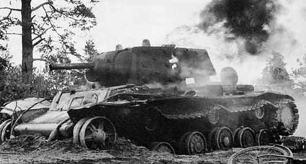
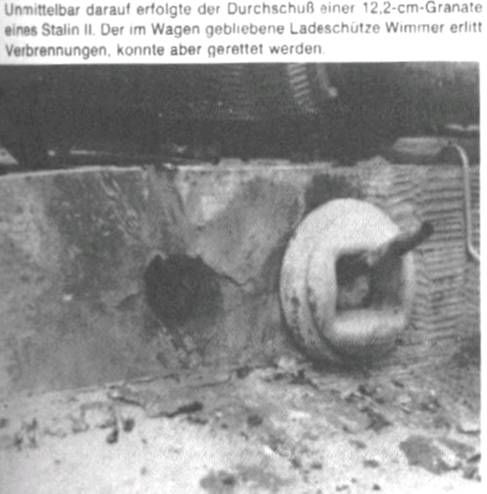
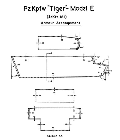
Welcome back to my blog for my weekly update. This week I have been busy trying to figure out the Hull shape and armour plating along side my road wheel placement. I quickly realised that there is a lot of conflicting dimensions out there when it comes to armour thickness and angling.
The values across all of the images are pretty similar across the board but the inconsistency was a little unsettling. In hind sight I spent quite a fair amount of time this week trying to look for decent reference to go from before I got my teeth stuck in.
I finally got a shape which I though was about right and started to split off the plates and thicken them to their correct armour thickness. I realise this week has been a bit of a slow one but I like to get this kind of thing as right as possible before I proceed to make sure I don't have and 'major' discrepancies towards the end of the build.
Having a bit of extra time at lunch I quickly arranged the road wheels into place as well so at least that's looking pretty pucker now =D
That takes me up to where I am so far. I hope you all have a great weekend and if you haven't already checked out Mechwarrior Online, go down load it and I will be playing over the weekend. Send me a friend request DNA87 and maybe we'll catch a game!
I started another Sphere challenge too at work (Yes I do actually do work at work other than these challenges) so I think I will try share that with you next week if I have time to finish it. Theme this time is egg so I'm sure you can come up with a few ideas of what I might be doing for that =)
Hi all and welcome back to my tiger tank weekly post.
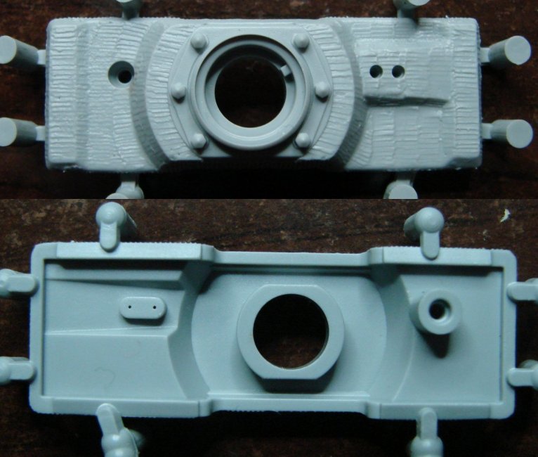
This week I have made a start on my mantlet for the Tiger Tank. I originally thought that there was only two variations of the turret mantlet, one from early production and one from its later production. This was mostly down to that there is one very visual difference between the two which is the reinforced bar that runs across the telescopic vision port holes. I didn't really have too much knowledge on that and took that visual difference as the main distinction between the two.
Late Production Mantlet
Tiger 131 Early Production Mantlet, Recognisable by the Visual Bar on the Right Being Absent
Looking around for more reference imagery I came across this image that illustrates the variations of mantlet during the tanks development throughout the war. It's pretty interesting to see how the shape changed and decisions made to aid the tanks combat performance.
A Good Illustration of Mantlet Development Thoughout the War
Adding sun shields and magnetic bomb protection were an obvious additions to aid the crew with vision and survivability. However the added armour to the telescopic openings and side cheek is not so obvious a decision. These must have been added to counter where the tiger was taking hits on the mantlet but this is me just speculation from the images I have seen from battle damage. it could also be a addition to accomodate additions to the internals but I will have a more in depth look at this for next week.
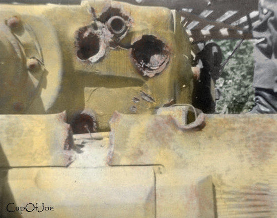
Battle Damage Mantlets
A Shell is Still Visible, Stuck in the Mantlet of this Battle Damaged Turret.
Here is how I have been getting on with my modelling for this week. I already had the gun sleeve modelled so I just had to use this as a base to build the mantlet around its shape. I know I had modelled the Sleeve with the correct radii and thickness's so this gave me the recess depth and shape for the mantlet as a starting point.
As you can see this is still a work in progress. I have a fair bit of work to do on this, cleaning up with some of the model pinching and also completing the back part of the mantlet where it connects to the trunnions. I'm pretty happy with the progression so far although its no where near done to the amount of detail I want to be. Part of my meticulous nature is that im never happy with what I've done when I've finished it. I guess this keeps me on edge to progress further with my work and continue to improve. Stay tuned for more updates on this one, the mantlet is one of the defining characteristics of the tiger and I definitely want to do this one right.
Thanks for your continued support and visiting of my blog, I very much appreciated. I hope you all have a good weekend (and if your in the UK a good bank holiday weekend) and I will catch you here next week for another Tiger tank progression report.
I thought I would give a quick update of where I am at with my Tiger. I've been concentrating on the little details that really start to pull this commanders cupola together and bring it to a close. I want to get this done in the next week as I have been spending a little too much time playing World of Warships. This is good for you meaning if your interested in this as I can give better ship reviews and work towards them all important higher tiered ships. I'm sure you all have your eyes set on particular ships that you will like to get if your waiting for access to the Closed beta. I am currently at tier 7 in the Japs destroyer line with my Hatsuharu ship.
Not my port but same pretty ship!
I have been looking for some decent reference imagery of this spring loaded hinge that aids the commander to open his hatch. Unfortunately I have been pretty unlucky with my efforts so from the images that I have been able to find I have had to still do some significant guess work with how this part works (if anyone has any decent close up pictures of this part from the 131 Tiger at Bovington Tank Museum it would be much appreciated) .
Any detail shots of this would be appreciated.
Here is my modelling work in progress with my early Tiger tank commanders cupola.Take care and have a good weekend and I look forward to seeing you back here at a later date to see my progress
Though I would give you a update on how I have been progressing on my Tiger Tank. With this week being bank holiday Monday in the UK (Over which I went to a music festival Dot to Dot Nottingham and saw lots of great bands such as Amber Run and Saint Raymond) I've only managed to fit in a little bit of modelling but now the Cupola is really starting to take form with those extra detail that really polish a model. .
This week I looked at modelling the hinge system that connects the hatch to the drum cupola. The hinge works on a 3 piece system with 2 hinges and a link to help close the lid on this great beast. The main Hinge seats underneath what looks like a spring system that would help the commander lift the hatch of his cupola. as the lid was 15mm thick it mush have been fairly heavy. The hatch diameter was 420mm lined with a thick rubber seal to prevent water form entering in deep wading and heavy weather conditions.
Tiger Drum Cupola
The hinge in itself seemed pretty complex for its purpose but the Tiger in general was notorious for being ridiculously over engineered. In WW2 to consider which nation had the least fuel and metal to come up with an idea for a fuel munching metal beast like the Tiger tank was almost insane.
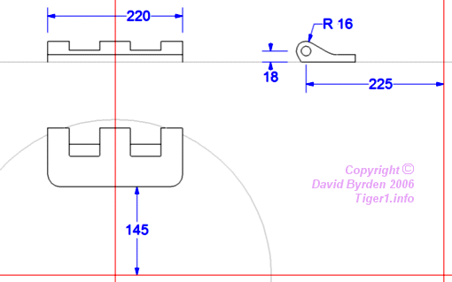
Hinge Technical Drawings
Above is the technical drawings of the commanders hatch lid hinge. I noticed that the fall off curvature from the hinge wasn't quite right in comparison to what is shown from Pictures taken of Tiger 131 in the Bovington Tank Museum. I altered my model whilst using the measurements given to more accurately depict the hinge.
Hinge Wireframe
Hinge Turbo Smoothed
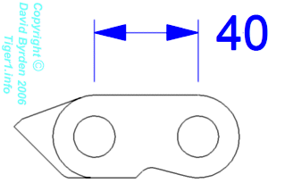
The eyelet that connects the two Hinges looks almost like a bike chain with a little extra to help the lid rest in a stable position when opened.
Eyelet Link technical Drawing
Wireframe of Link
Turbo Smoothed Link
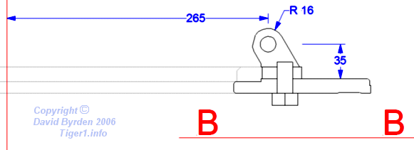
The final bit of the hinge is now the bit that is connected to the drum itself. its more or less the mirror of the first hinge I made but with a few different features.
Second Hinge Technical Drawing
Wireframe of Second Hinge
Turbo Smoothed Second Hinge
So the top of the Cupola is starting to take shape now, I have a few more things to do then I can add the 18 degree offset to the top details. Its just easier to keep things this way until the end as any 3D person will know.
Progress So Far =)
What the Top of the Cupola Will Look like with the 18 Degee Offset
That's all for this week, I hope to catch you back here soon. Till then take care and have fun playing what every you play. Before I go I would like to thank the Tiger website I have been using for all your technical drawings. You have been a great resource. Find the link to it here
I did plan to get this post out over the weekend but as things fate conspired against me (i.e. a USB stick had a untimely death when going back to a family event) so I will get this post out as part of my first double post this week. This is just a quick update on How I have been getting on with my Tiger tank and a little sneak preview of my working process.
After doing a bit of searching about the look of the Tigers there are 2 distinct types of cupola. The earlier drum cupola mounted in earlier versions gave the commander a higher point of view when viewing the battle field but left his head quite exposed. For those of you that play world of tanks you will be used to seeing the later style turret on the Tiger though I'm not quite sure where the first turret that tiger uses comes from as I have seen no imagery of that style of turret been fitted to a tiger (anyone fancy giving a comment on that would be interesting)
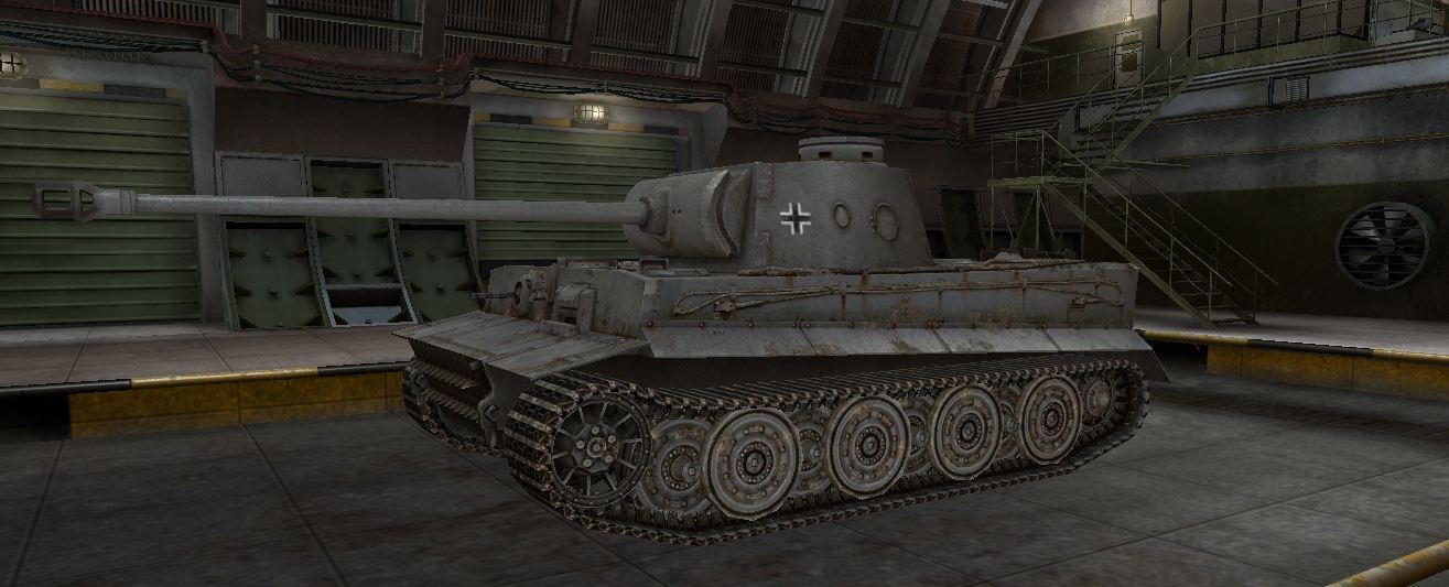
The asymmetric turret everyone recognises with the Tiger Tank
What is this turret? Stock turret in WoT but when was this used?
When most of the tank from the front had 100mm of armour, which on a ideal engagement would be facing the enemy at a 45 degree angle, made the effective armour around 140mm ish thick (without the proper maths done). A direct shot to the commanders cupola assuming the shot hits on a dime, is only 75mm. Though hitting a drum design exactly at perpendicular angle is pretty hard to go when engagements for tigers were mostly at long range.
Older Drum Design Cupola
Later Tigers incorporated a flatter design which was adopted onto the kind tiger and a similar variety onto the Panther. This cupola design saved on materials needed to build it as well as reduced the vulnerability of the commanders head to fire.
Later variant of Tiger shown by the later varient of cupola, road wheels and gun mantlet
Building the Tigers early cupola really highlights how complex the tank was in comparison to Russian and American tanks. Designed for deep wading up to 4 meters the tank had to have drainage holes cur into areas which water would collate. The 10 round holes cut into he top of the cupola allowed water to drain off from the cupola lid whilst having a 18 degrees offset so the water did not run off directly into the vision slits lower down (very early editions of this cupola had drainage holes above the view ports before this error was noted).
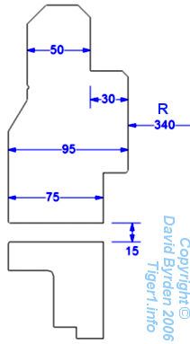
The thickness of the armour variates throughout the drums total structure but on the whole it maintained a 75mm thickness along the main body that covered the commanders head.
Cut through of thickness for tigers Drum Cupola
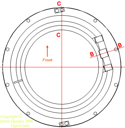
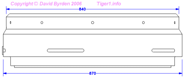
The Diameter slightly as well as shown in the image below.
Diameter of different parts of the Cupola
All these reference images for sizes and positions are from www.Tiger1.info which has been a amazing site for technical information throughout this project so far so I can't recommend it enough.
Doing 3D meshes with cuts in always presents a challenge of how best to position your geometry to best get what you are trying to achieve whilst keeping your mesh tidy. This is again harder in cylinders as securing lines in the wrong areas cause pinching. Without creating my own tutorial which would be pointless there is loads of tutorials out there on youtube and this in particular tutorial shows exactly how I structure my geometry when I created my Cupola.
I went one step further than this guy however by figuring out the maths about where I could place my cuts along the Circumference of the cylinder to get the geometry to seat in the exact positions I wanted them too. In short I figured out the circumference, (because I knew the Diameter I could figure out the circumference which is C=πd) then set out cylinders with the exact lengths (for the view port slits in the cupola) and diameter (for the drainage holes) then bent the boolean'd mesh around a central point to create a cylinder. This may be hard to visualise in your head so ill put some pictures below.
Doing this method should in theory place the cuts from the boolean in the exact place they should be if its a perfect circle.
After a little bit more work that what I have shown you here this is where I am with the Cupola. I still have more work to go with it like creating the welds for where it connects to the turret and the hinge to model but I'm fairly pleased with the result. The cylinder still has a little bit of pinching but its pretty negligible
The Un-Subdivided Wireframe Mesh
The Smoothed Mesh (turbo smoothed)
Smoothed Non Wireframe Result WIP
This is where I am so far, working full time means little time for me to do my own work but its important that I keep it up share and review it for my own self progression. Thats all for now, I hope you've enjoyed this little snippet of my work and keep looking back as I battle my way through this bad boy to create a banging looking Tiger tank.
I mentioned in my last post that I had started modelling one of my favourite tanks of all time, The Panzerkampfwagen Tiger Ausf E or Tiger as it was officially nicknamed by Ferdinand Porshe
The Order for the deveopment of a 45 ton heavy tank with a 88 caliber gun was put forward to Porsche and Henschel after Nazi Germany ran into trouble fighting T-34's and KV-1's in Operation Barbarrosa. The Current Panzer 3 that the Germans were fielding had the 5cm KwK 38 L/48 which was only capable of beating the armour of a T-34 at close range at the side or rear.
The KV-1 was impervious from every angle the panzer 3 shoot at it from, even at close range. The Flak 8.8cm was the only gun that the German forces had deployed that had the power to defeat the T-34 on its frontal armour and stop a KV-1 dead.
So the after the designs for a 45 ton Heavy tank were submitted it was the Henschek tank design that was taken forward to mass production. With 100mm of frontal armour, the Flak 8.8cm modified for tank use and the 21.35 litre 650hp engine even in its early stages it was a formidable beast.
The Tiger Tank although a superior weapon was famous for how complex its design was. The Tiger Cost double the amount that a Panzer 4 cost to produce and 4 times as much as a Stug 3. This accounted for the short number that were deployed in World War 2 and also why so many Tigers exist in decent condition today (not many survived the war and post war scrapping).
Bovington Museum houses the only running Tiger, the 131 that reciently featured in 'FURY'. A movied up untill the last fight scene believably reconstructs a tankers life in combat.
In later Stages of the war other nations tanks had started to incorporate guns that were capable of countering the tigers armament such as the British 17 Pounder Gun and the Russian 122 mm Gun.
So with the brief history of the Tiger out the way I can give you a bit of a update on what I have been doing to give reconstruct this beast of a tank.
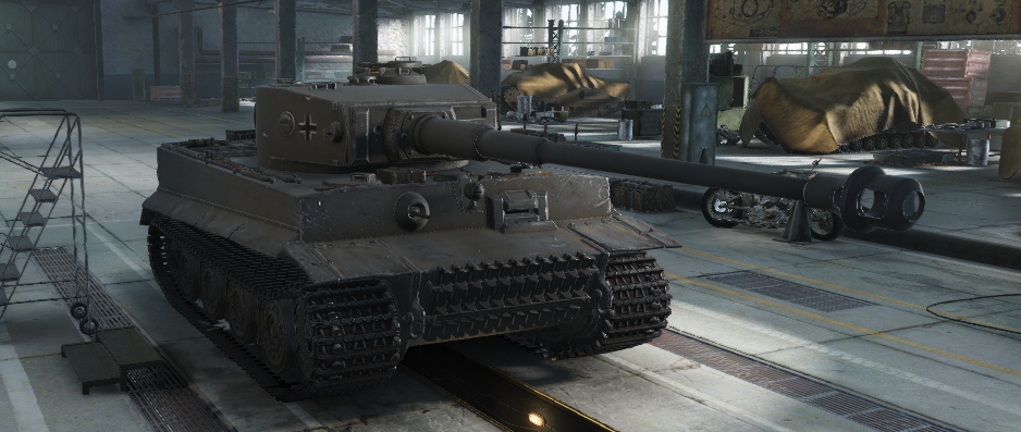
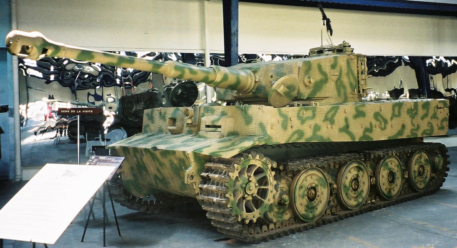
I Decided that I would like to go about recreating a early production model of the Tiger Tank. Unlike the picture above which is a late model. After my usual reference finding and image collating
I decided to start with the Turret as this really gives the Tiger its silhouette a defining shape. I started modelling the turret and ended up finding too many discrepancy's with the blueprints that I had collected found. I did a bit more research and found a amazing site that I started working from. Most of my reference of Tigers have come from this site which is amazing by the way and I recommend anyone who is modelling a Tiger to check this out http://tiger1.info/ . Blue Prints are great for getting a overall shape but there is far too many times for my liking that blueprints don't line up perfectly so i wouldn't trust just one set by its self until I have done some proper research.
Initial Block Out
When I figured things Weren't quite right
Remodelling bits to measurements and specifications using old modelled parts
The turret is quite a interesting, the first thing to note its a asymmetric design with 80mm turret wall armour all around in one piece of metal. The turret top armour in early models was 25mm thick, so having these two thicknesses positions and how they slotted together getting the innitial shape for the tank was pretty easy.
I then moved on to the loaders hatch and vent getting them nicely detailed up. www.tiger1.info has all the measurements by a guy that was building a CAD model so I cant fault the amount of resources this guy has put together to get a accurate result.
Being lazy or unwilling to try modelling welding at this point really I have had to give it a shot to see what I could come up with so admittedly this is a work in progress to get the right results but anyone that has tried to get a good looking weld will know there isn't a lot of tutorials out there to get amazing result (if you know of some please throw them my way =) ) but I managed to get this result using deformed spheres welded together so they are all in quads. (I may get a tutorial together after I have finished to show you how I have done it if your lucky =P)
Im going to continue to Develop this weld technique so I can get it looking pucker as there is going to be many weld lines in this tank. My next focus is once I have a way to get welds looking nice I will work it into my hatch and air vent where required them move onto the commanders cupola and support bars at the front of the turret ready for the cheek mountings and mantlet to be introduced.



















,_Panzer_III.jpg)